APPLICATION :
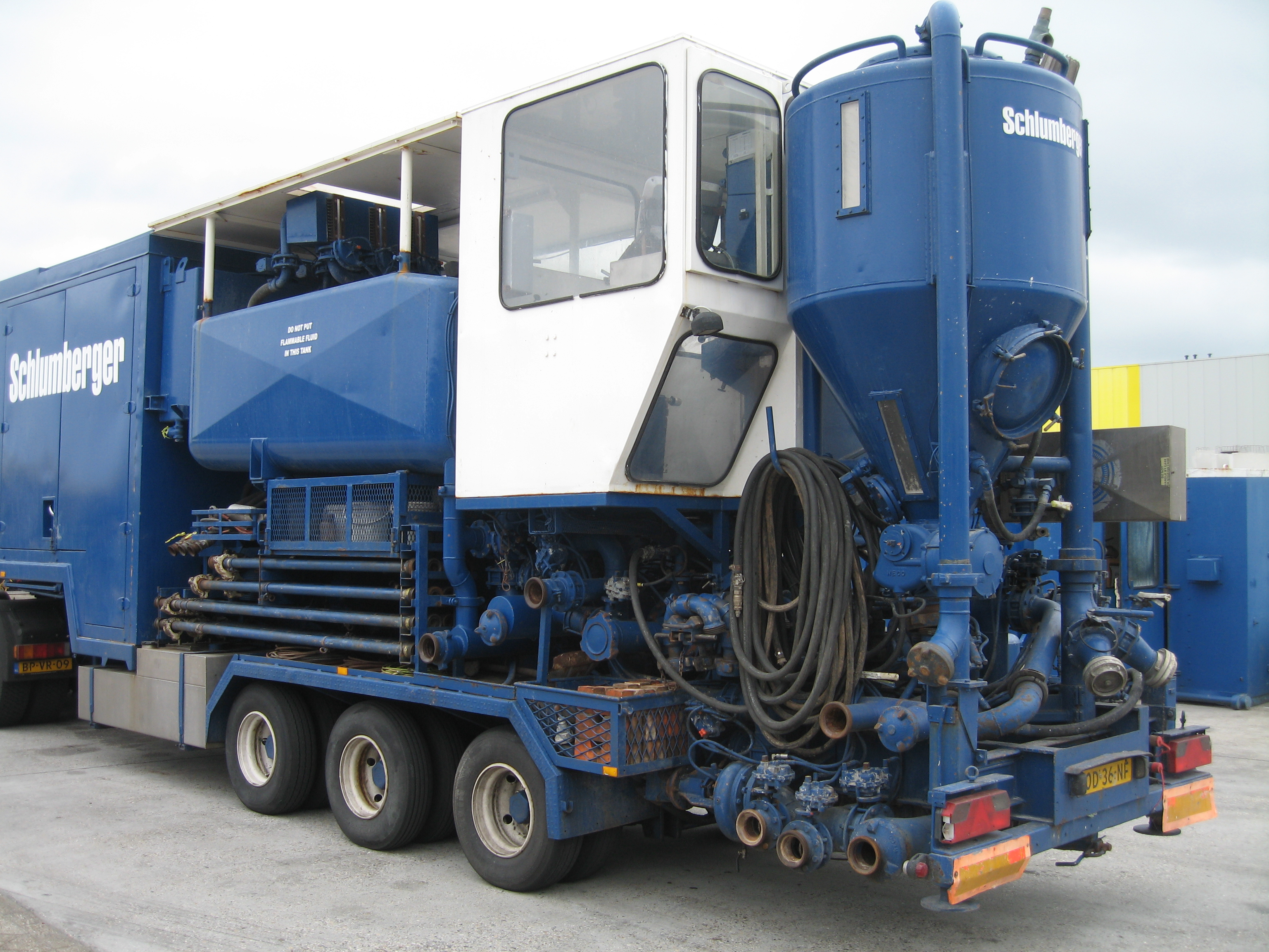
- Provides dry material storage for oilfield use.
- Used to fill up a bulk plant.
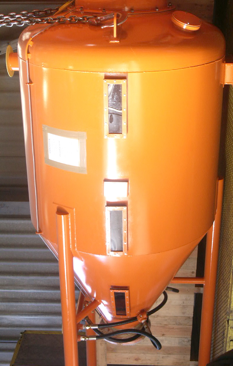
The surge tank is designed to receive cement, bentonite, baryte, from bulk plant or trailer and to supply dry materials for mixing with a bowl or PCM (Process Control Mixer).
The fill and vent line are located on the side for easy acc- cess.
A vent line is available for use with a dust collector. The pressure relief valve provides safe unloading.
The interior is designed to allow dry material to flow out under air pressure.
The silo is equipped with multi-section air pad which requires minimum maintenance.
Manholes are located for easy access.
| ON-SHORE | OFF-SHORE | |
|---|---|---|
| Norms : CODAP or ASME VIII | CODAP or ASME VIII | CODAP or ASME VIII |
| Diameter : mm (Ft) | 1600 mm (5 Ft) | 1600 mm (5 Ft) |
| Design Pressure : Bar (PSI) | 4.1 Bar (61.9 PSI) | 4.3 Bar (65 PSI) |
| Working Pressure : Bar (PSI) | 2.8 Bar (42.3 PSI) | 4.3 Bar (65 PSI) |
| Working Temperature : C° | – 20 C° to 50 C° | on request |
| Test Pressure | 6.2 Bar (93.7 PSI) | on request |
STANDARD DESIGN :
As follow vessel Code to CODAP or ASME VIII – Approved by DNV or BV – Heavy Duty Skid – Relief Valve Set Pressure – Fill Line OD – Discharge Line OD – Vent Line OD – Air Pad – Skid Type
OPTIONS :
Special design and equipment on request.
| SPN | DESCRIPTION | CAPACITY |
|---|---|---|
| SU. TA / 70 | Surge Tank, on 3 steady legs | 70 CuFt |
| SU. TA / 120 | Surge Tank, on 3 steady legs | 120 CuFt |
| SU. TA / 160 | Surge Tank, on 3 steady legs | 160 CuFt |
| SU. TA / 70-TJ | Surge Tank, on 3 steady legs, 2 toggle-joints | 70 CuFt |
| SU. TA / 120-TJ | Surge Tank, on 3 steady legs, 2 toggle-joints | 120 CuFt |
| SU. TA / 160-TJ | Surge Tank, on 3 steady legs, 2 toggle-joints | 160 CuFt |